
Variable Transformers
INFO
These work just like the default transformers, but they use a signal to automatically adjust voltage.
How to Use
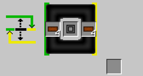
To make the transformer work, place four copper cables in slots 1 and 3, and a ferromagnetic core in the center. For more details on how this works, see the default transformer page.
The Main Difference
Variable transformers adjust voltage based on an input signal. This signal must come from a side that is not green or yellow.
With the default transformer, it doesn't matter which side you use for input or output. You can adjust the voltage using slot 1 or 3 on either side.
However, the variable transformer works differently:
- To increase voltage, input power on the yellow side and output on the green side.
- To decrease voltage, input power on the green side and output on the yellow side. In both cases, the signal controls how much the voltage changes.
Basic Examples
Here are some basic examples to get you going.
Inventory
Step Down Voltage
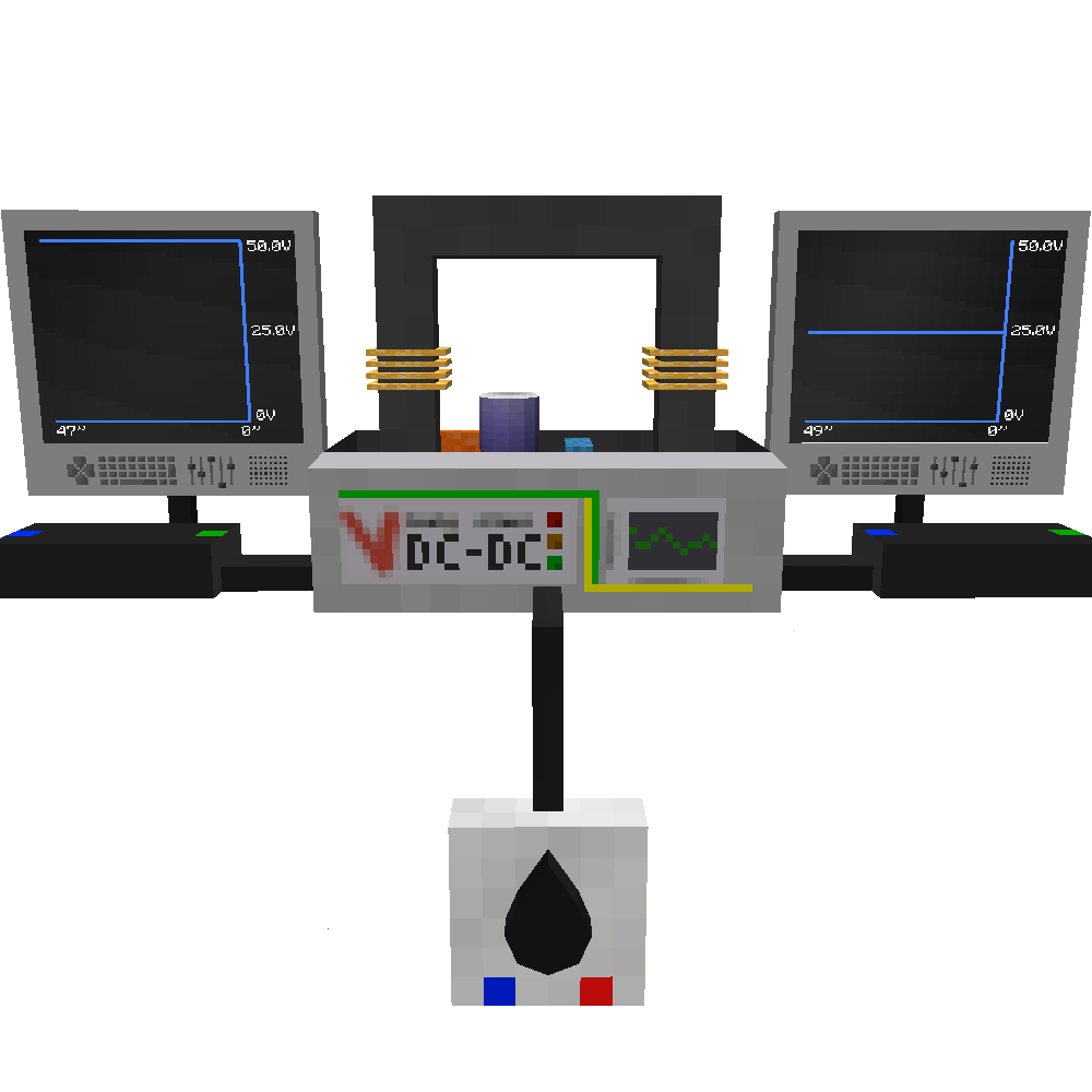
In this example: A 50V input is connected to the green side, and the output goes to the yellow side. A signal of 2.5V (which is 50%) is applied, resulting in a 25V output.
Step Up Voltage
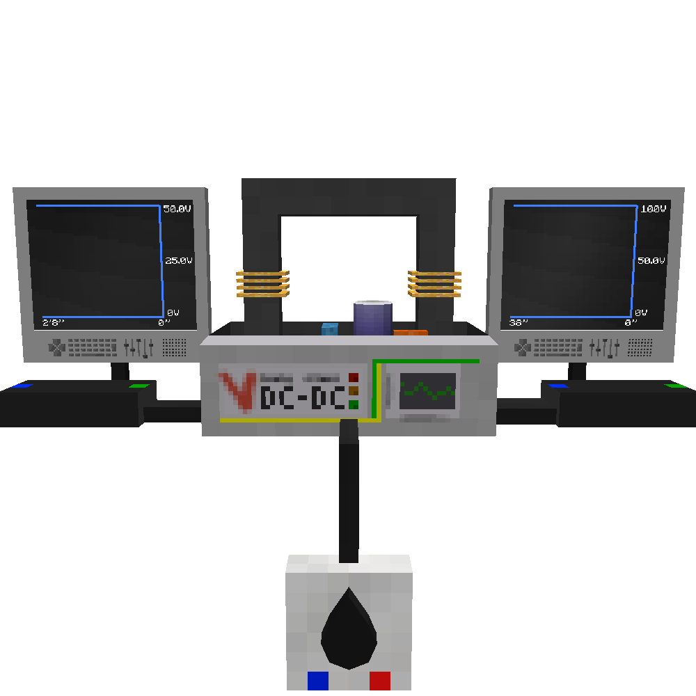
In this example: A 50V input is connected to the yellow side, and the output goes to the green side. A signal of 2.5V (which is 50%) is applied, resulting in a 100V output.
Advanced Examples
Here is an example of how to automatically adjust voltage when you want a fixed output but have a variable input voltage.
Step Down Voltage
| Electrical Probe | Signal Processor |
|---|---|
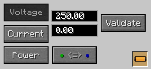 |  |
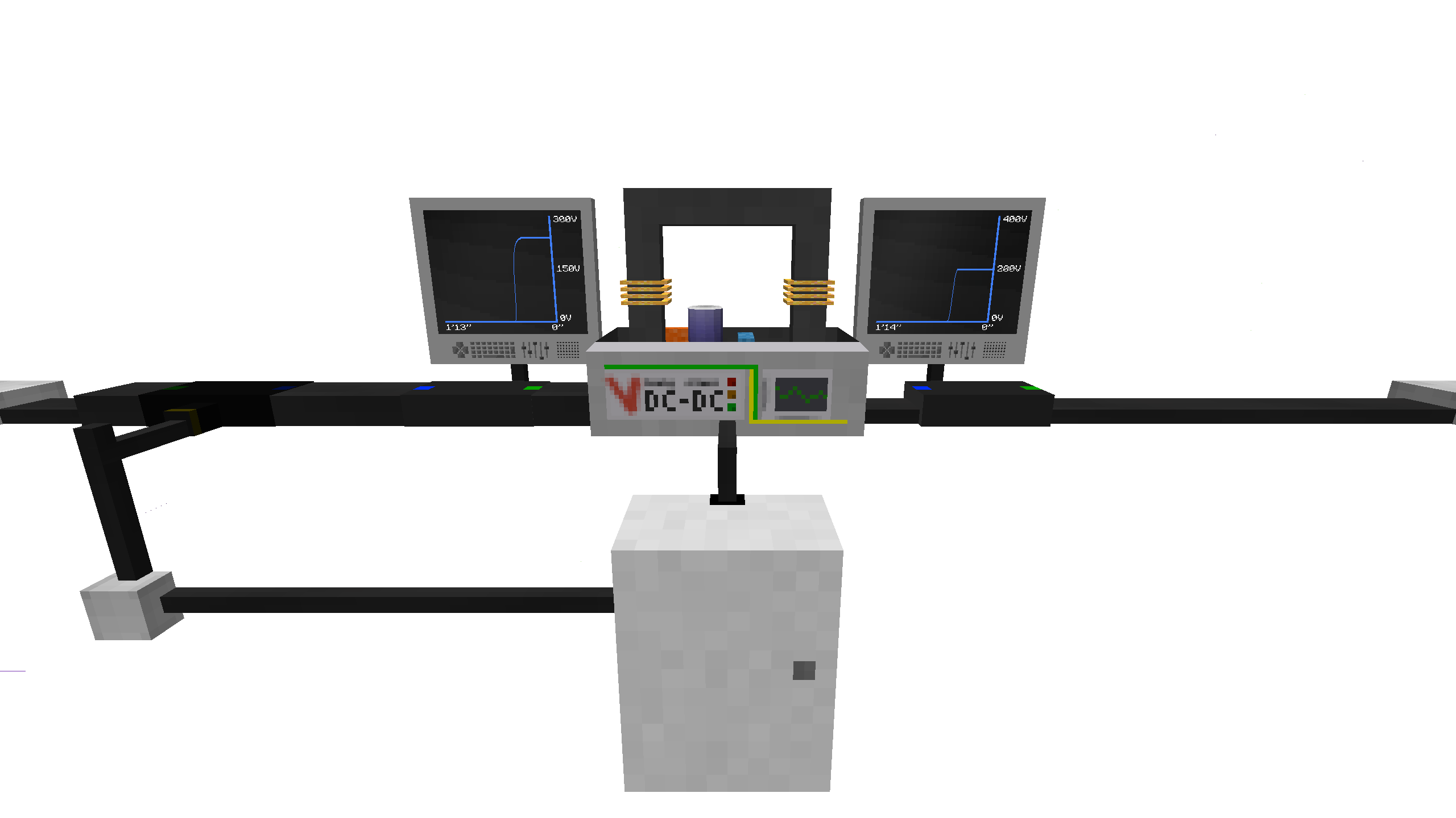
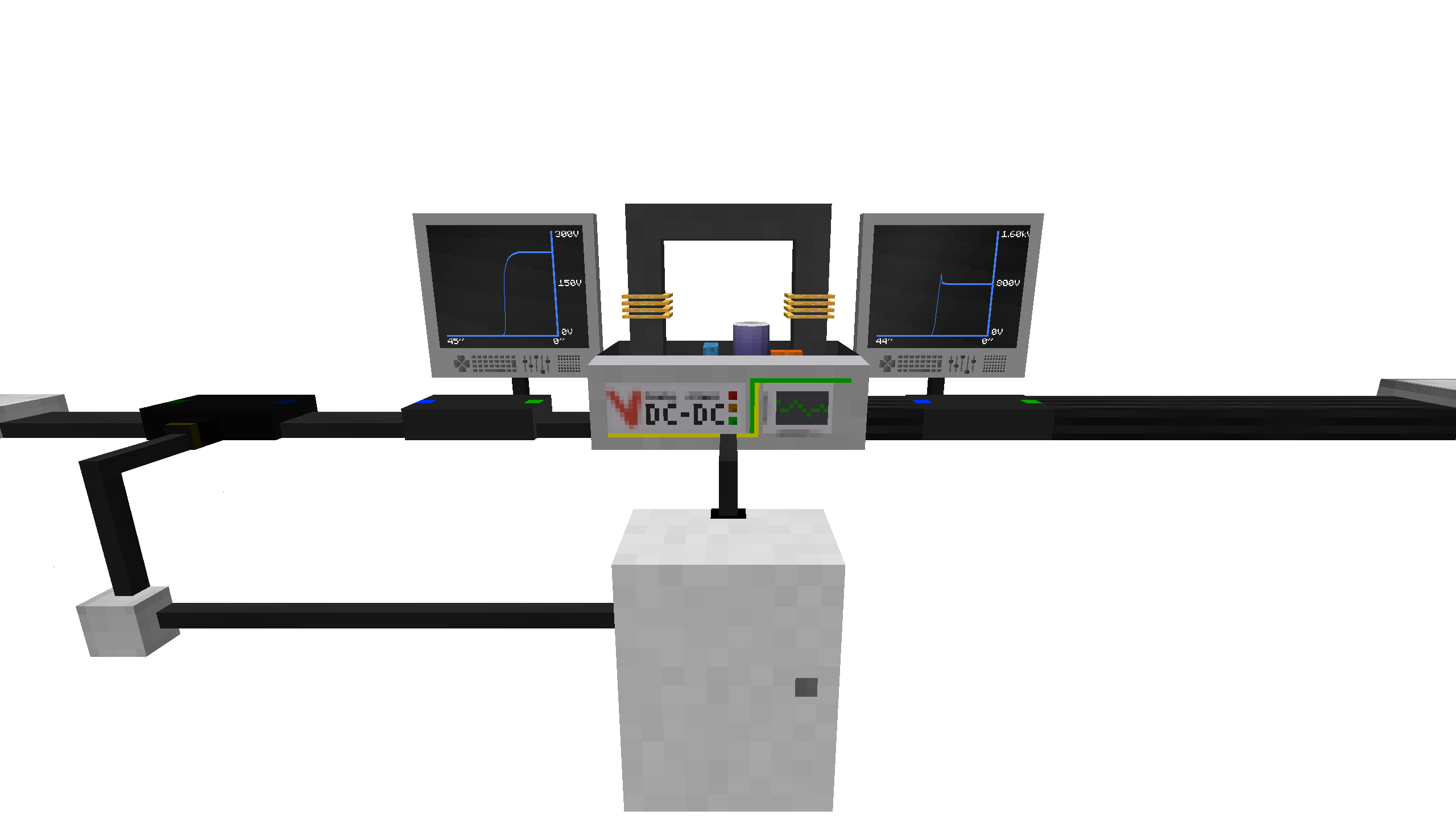
In this example: A variable input voltage between 200V and 250V is connected to the green side. The output is sent to the yellow side. An electrical probe reads the voltage and sends it to a signal processor. The processor uses the formula 1 - (0.8 / A) to control the signal, which keeps the output at 200V.
This method can be used with different voltage levels. You only need to adjust the probe reading:
- To get a stable 3200V, the probe must read 4000V for 100%
- To get a stable 800V, the probe must read 1000V for 100%
- To get a stable 200V, the probe must read 250V for 100%
Step Up Voltage
| Electrical Probe | Signal Processor |
|---|---|
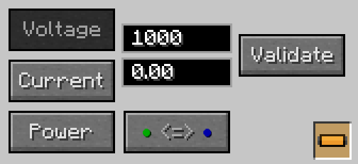 |  |
In this example: A variable input voltage between 200V and 250V is connected to the yellow side. The output is sent to the green side. An electrical probe reads the voltage and sends it to a signal processor. The processor uses the formula 1 - (A / 0.8) to control the signal, which keeps the output at 800V.
This method also works for different voltage levels. Just change the probe reading:
- To get a stable 3200V, the probe must read 4000V for 100%
- To get a stable 800V, the probe must read 1000V for 100%
- To get a stable 200V, the probe must read 250V for 100%